Overview
IMU (Inertial Measurement Unit) is widely used in the industry and for hobbyists as well. In general, it can perform accurate measurement of acceleration, angle rate and/or magnetic field, which can be then processed to obtain different useful parameters, such as Euler’s angles (roll, pitch and yaw).
In this post, we will discuss about the basic use of MPU6050 – one of the most affordable but powerful IMUs, on Arduino and mainly focus on the conversion between raw data to the Euler’s angles. This particular IMU has 6-DOF (Degree of Freedom) by combining an accelerometer and a gyroscope.
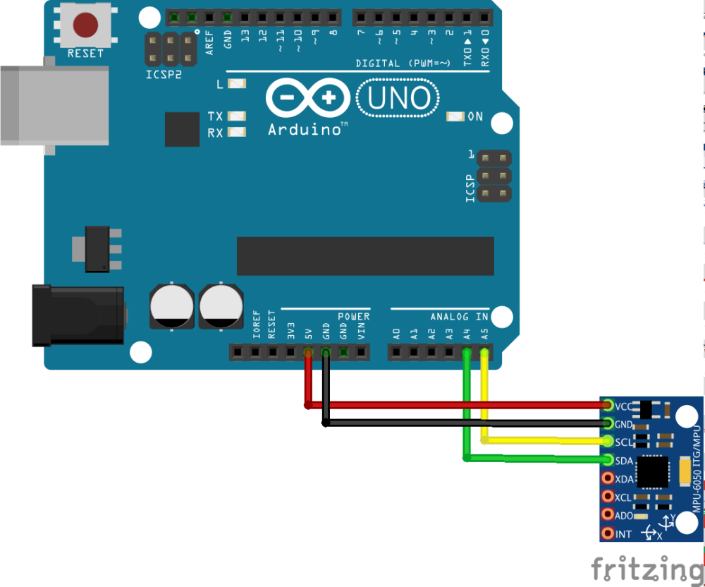
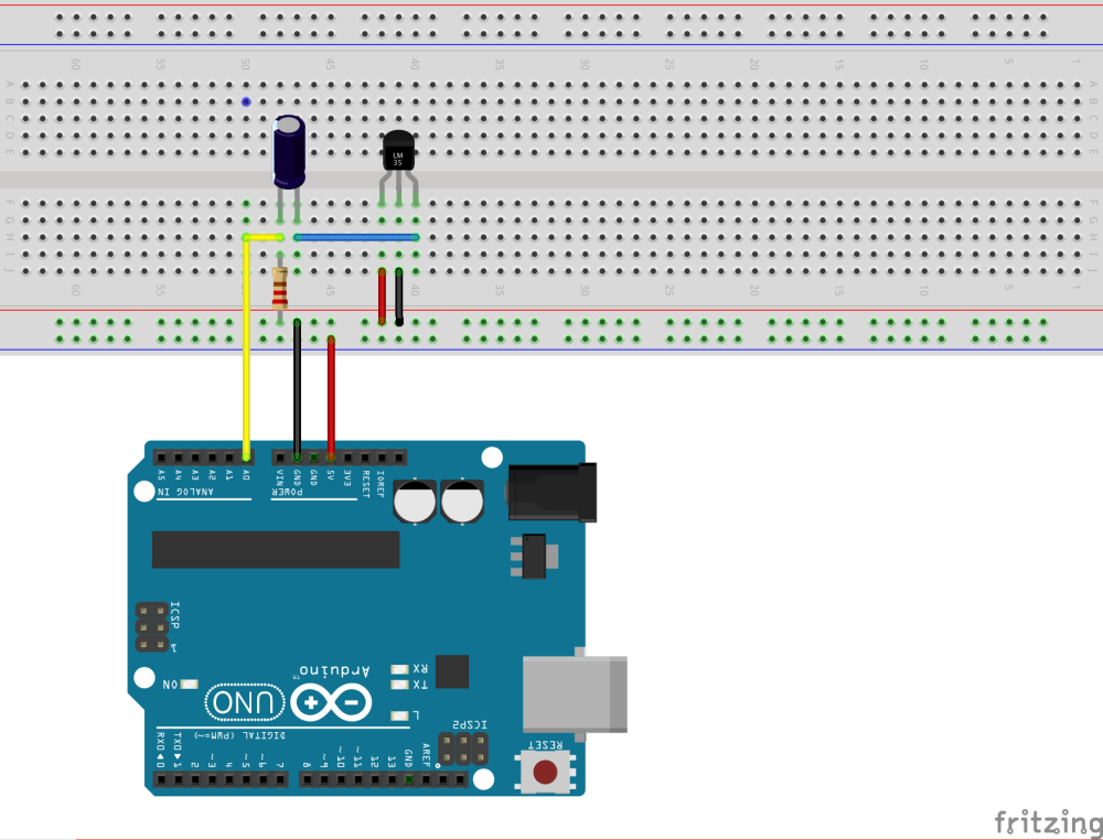
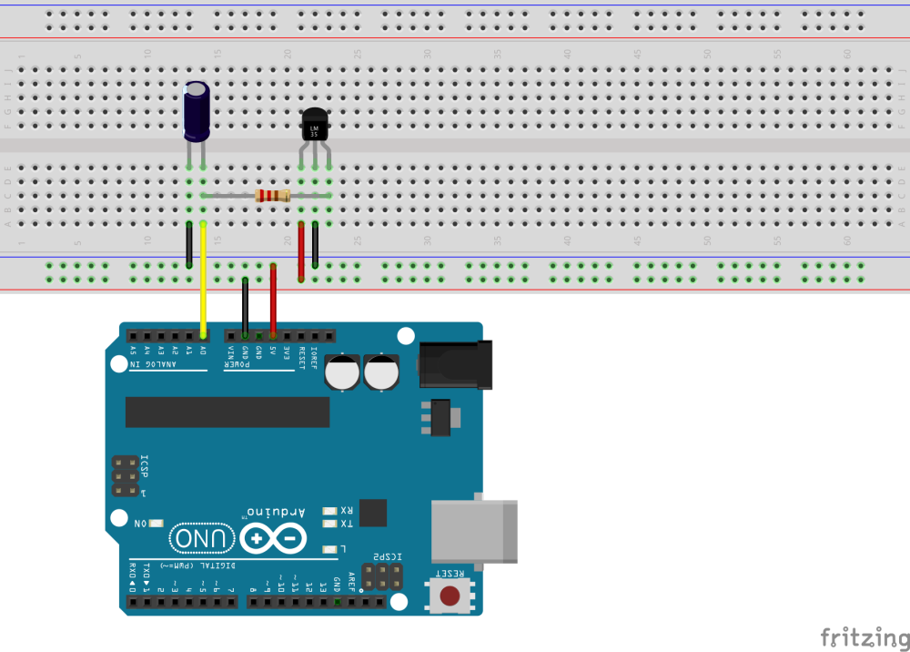
Connection Diagram
The MPU6050 is design for I2C (Inter-Integrated Circuit) Communication, also known as IIC, between MPU6050 itself and other devices, such as Arduino or other MCU.
Retrieving Raw Data and Data Conversion
Unless you are an experienced programmer or computer engineer, in which case you probably do not need this article, it might be rather difficult to read the values from the IMU without struggling. Therefore, we would use a developed library from Jeff Rowberg, who is well known for his arduino library – “i2cdevlib”. We will use one of the sub-libraries inside the “i2cdevlib”, namely the MPU6050 library, which can be downloaded here. Make sure you download all files, except for the folder “examples”, and put them in the same directory of your Arduino sketch.
Let’s look at the code of how to read the raw data and convert it to euler’s angles.
#include "I2Cdev.h"
#include "MPU6050.h"
#include "Wire.h"

// class default I2C address is 0x68
// specific I2C addresses may be passed as a parameter here
// AD0 low = 0x68 (default for InvenSense evaluation board)
// AD0 high = 0x69
MPU6050 accelgyro;
//MPU6050 accelgyro(0x69); // <-- use for AD0 high

int16_t ax, ay, az;
int16_t gx, gy, gz;
int16_t roll_a, pitch_a;
int16_t roll = 0, pitch = 0;

void setup() {
    Wire.begin();

    // Initialize serial communication
    // Remember to set your computer's baud rate to 9600 as well
    Serial.begin(9600);

    // Initialize device
    Serial.println("Initializing I2C devices...");
    accelgyro.initialize();

    // Verify connection
    Serial.println("Testing device connections...");
    Serial.println(accelgyro.testConnection() ? "MPU6050 connection successful" : "MPU6050 connection failed");

}

void loop() {
    // Read raw accel/gyro measurements from device and save them in ax, ay, az, gx, gy, gz
    accelgyro.getMotion6(&ax, &ay, &az, &gx, &gy, &gz);

    // These methods (and a few others) are also available
    //accelgyro.getAcceleration(&ax, &ay, &az);
    //accelgyro.getRotation(&gx, &gy, &gz);

    Serial.print("ax ay az: ");
    Serial.println(ax + " " + ay + " " + az);
    Serial.print("gx gy gz: ");
    Serial.println(gx + " " + gy + " " + gz);

    // Calculate the Euler's Angle using accelerometer
    roll_a = (atan2(-ay, az)*180.0)/M_PI;
    pitch_a = (atan2(ax, sqrt(ay*ay + az*az))*180.0)/M_PI;

}
Applying Filters
There are a variety of choices in filters used for IMU, for example, Kalman Filter, Low-Pass & High-Pass Filters, Complementary Filter. In this tutorial, I will combine the use of low-pass filter, high-pass filter simply because they are very easy to understand and implement. If you are not familiar with low-pass and high-pass filters, please take a look at Implementation of Filters on Arduino.
A simple implementation of the filters for MPU-6050 is shown in the figure below:
// Put this block before void setup()
const float alpha_lp = 0.5; // Change this to the value you need
const float alpha_hp = 0.5; // Change this to the value you need
// Last read value ax, ay, az, gx, gy, gz
int16_t ax_l = 0, ay_l = 0, az_l = 0;
int16_t gx_l = 0, gy_l = 0, gz_l = 0;
// Filtered value ax, ay, az, gx, gy, gz
int16_t ax_f = 0, ay_f = 0, az_f = 0;
int16_t gx_f = 0, gy_f = 0, gz_f = 0;
// Put this block inside the void loop() after retrieving data.
// Low Pass Filter for accelerometer
ax_f = alpha_lp * ax + (1 - alpha_lp) * ay_f;
ay_f = alpha_lp * ay + (1 - alpha_lp) * ay_f;
az_f = alpha_lp * az + (1 - alpha_lp) * az_f;

// High Pass Filter for gyroscope
gx_f = alpha_hp * (gx_f + gx - gx_l);
gy_f = alpha_hp * (gy_f + gy - gy_l);
gz_f = alpha_hp * (gz_f + gz - gz_l);

// Save the last read value into ax_l, ay_l, az_l, gx_l, gy_l, gz_l
gx_l = gx; gy_l = gy; gz_l = gz;
ax_l = ax; ay_l = ay; az_l = az;
Remember to use to filtered value to calculate the Euler’s Angle or do any calculation instead of the raw value. Otherwise it lost the purpose of filtering.
Now, you might be wondering why do we need the reading from gyroscope if we can calculate the Euler’s Angle from accelerometer, or vice versa. The truth is, even with low-pass filter, the accelerometer is still noisy, and the gyroscope will still drift a bit. Therefore, we need to combine them together, i.e. IMU fusing. This can be done by different technique, e.g. Kalman Filter, Complementary Filter, Mahony AHRS Algorithm, etc., but we will use the simplest method here – complementary filter.
// Put this block before void setup()
const float alpha_com = 0.95;
float timer_ini = 0;
float dt = 0;
// Put this block right after void loop()
timer_ini = millis();
// Put this block inside the void loop() after filtering data and calculating angle from accelerometer.
roll = alpha_com * (roll + gx_f * dt) + (1 - alpha_com) * roll_a;
pitch = alpha_com * (pitch + gy_f * dt) + (1 - alpha_com) * pitch_a;

dt = millis() - timer_ini;
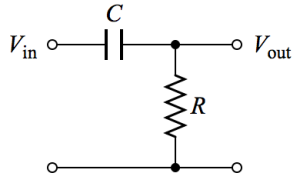
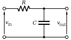
 across the capacitor
  and resistor
  , and the output signal
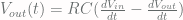
  across the resistor
  can be calculated from the time constant (
 ), which is inversely proportional to the cutoff frequency:
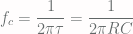
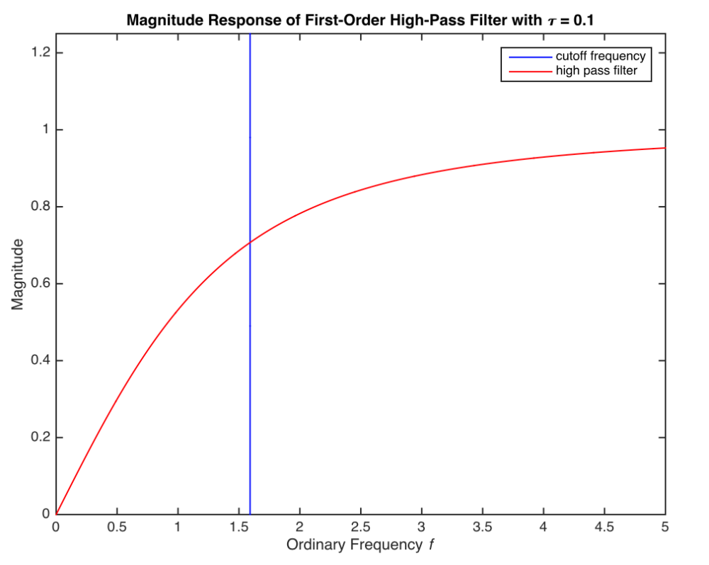
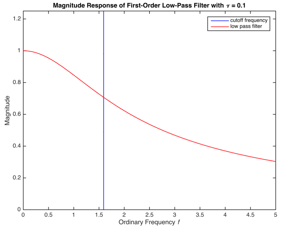
 should be carefully chosen in order to achieve the desirable magnitude response, hence filtering effect.
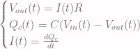
![x[n]](https://s0.wp.com/latex.php?latex=x%5Bn%5D&bg=fffdfd&fg=606666&s=0&c=20201002) ,
, ![y[n]](https://s0.wp.com/latex.php?latex=y%5Bn%5D&bg=fffdfd&fg=606666&s=0&c=20201002) , and discretize the differentiation, we can get a simple result:
, and discretize the differentiation, we can get a simple result:![y[n]= \alpha(y[n-1]+(x[n]-x[n-1])) \quad where\ \alpha = \frac{RC}{RC+\Delta t}](https://s0.wp.com/latex.php?latex=y%5Bn%5D%3D+%5Calpha%28y%5Bn-1%5D%2B%28x%5Bn%5D-x%5Bn-1%5D%29%29+%5Cquad+where%5C+%5Calpha+%3D+%5Cfrac%7BRC%7D%7BRC%2B%5CDelta+t%7D&bg=fffdfd&fg=606666&s=0&c=20201002)
 ), we can get different response and effect.
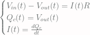
![y[n] = \alpha x[n] + (1-\alpha)y[n-1] \quad where\ \alpha = \frac{\Delta t}{RC+\Delta t}](https://s0.wp.com/latex.php?latex=y%5Bn%5D+%3D+%5Calpha+x%5Bn%5D+%2B+%281-%5Calpha%29y%5Bn-1%5D+%5Cquad+where%5C+%5Calpha+%3D+%5Cfrac%7B%5CDelta+t%7D%7BRC%2B%5CDelta+t%7D+&bg=fffdfd&fg=606666&s=0&c=20201002)
